Qudio Player
An easy-to-use music player for children based on the Raspberry Pi Zero and the JBL On Stage IIIp (again)
In spring 2016 I finalized the "Musikrakete", a music player that our boys could operate without assistance. Later on, there was a second version. This is the third version, with all of the improvements I came up with during the last three years. It is easier and cheaper to build, the case is way smaller and much more robust. By switching to volumio the player now supports remote control from the phone and streaming services like Spotify. This is all combined with the existing features like playing MP3s from the local network and, most importantly, being easy to use even for small children. So if your children love music and audio books just like mine, this might be a project for you.
The Idea
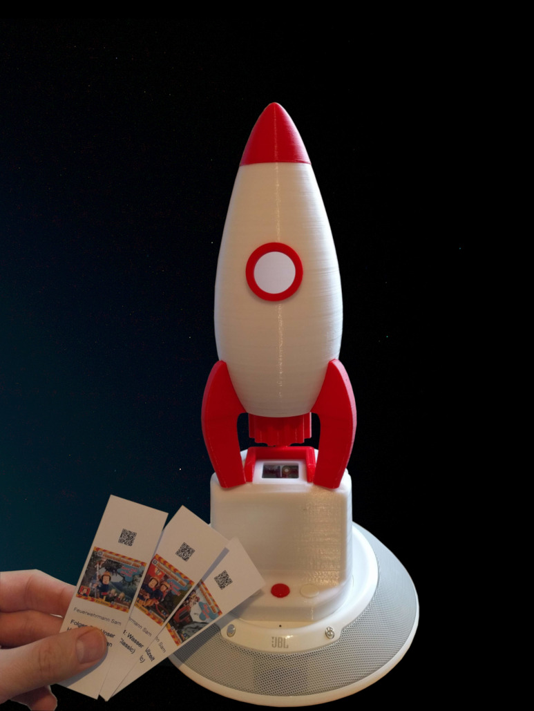
This project started in 2016, when Anica asked me if buying a hörbert MP3 player would be a good idea. At the time our boys wasted two to three CDs every week, trying to get some music out of the small player in their room. And the player in the living room also seemed to reach its end of life pretty soon due to their enthusiasm. Still I wasn't too sure about this hörbert thing. In order to get new files on the SD card of the player, the case had to be opened, the navigation with 11 buttons seemed a little confusing and a single speaker operated with four batteries also did not seem promising to me.
I had seen a project description of an MP3 player for small children shortly before: A Raspberry Pi mini computer, connected to a webcam and speakers, reads QR codes and plays the respective track or playlist. So this was what I suggested and to my surprise it was considered a better solution right away. And I had a project.
As good as the project description seemed to be, I wanted to make some improvements on the original design: The player should detect the QR automatically, it should have buttons for play/pause and skipping and all components should be put together in a single case. Most importantly, the MP3 files should be delivered directly from our home server. No SD card replacement needed.
Since we had an old JBL On Stage IIIp speaker lying around that wasn't used anymore due to its outdated iPhone dock connector, I decided to use this as a base. After playing around with Onshape, soldering and programming for three months, I had the Musikrakete ready by end of March 2016. It was a huge success with the boys and has been in heavy use ever since.
Over the last years I came up with some improvements on the original design and created a second version. But I always had some things in the back of my mind that I wanted to make better about both the hard- and the software and when the little brother moved into a room of his own, I knew it was time to bring all that to life. So this is the smaller, better and cheaper third version. The rocket on top is optional, by the way. But little brother would never have accepted a player that did not somehow include a rocket, since the original, rocket-shaped design is still used by the older one.
PiPlayer 3.0: Qudio
This third version now relies on volumio which can play music from streaming services like Spotify Premium or LastFM, has a nice web interface and makes configuration easy. The case is much smaller than before, which makes it sturdier and easier to print. The electronic parts are all easily obtainable standard compontents and even cheaper than before. Again, it is built on top of the JBL On Stage IIIp speaker, that can still be found on ebay for little money and provides a perfect base for a player like this.
The main component is now a Raspberry Pi Zero W, that can be run off the dock connector without an additional power source. I replaced the Pimoroni PHAT DAC with a dirt cheap audio module based on the same chip. The IR sensor that detects the QR cards is now a ready-made module which makes assembly easier. The buttons have been replaced by the ubiqitous standard components that come with every Arduino starter kit.
Parts list
- JBL On Stage IIIP
- The case, which consists of four parts. I printed mine in standard PLA.
- Raspberry Pi Zero W with a micro SD card
- CJMCU-5102 plus a 10 kΩ resistor, some other PCM5102A based module or any other I2S DAC that is supported by volumio. Search for 'pHAT DAC'. A USB sound card will not work, since the USB port is used by the webcam.
- TCRT5000 reflective sensor module
- The ultra-cheap USB webcam that can be found on ebay, aliexpress and the like (just sort for price). Some versions come with a small cable reel. This fits perfectly in the holder at the bottom of the case.
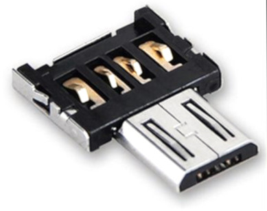
- USB A to micro USB adapter that connects the webcam to the Raspberry Pi's micro USB port
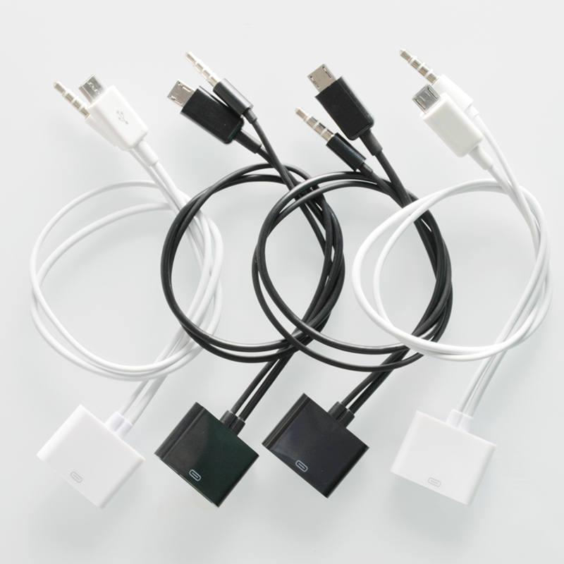
- 30-pin Apple dock adapter to micro USB and 3.5 mm audio
- White LED (preferably diffused) for illumination of the QR cards with a proper resistor
- 3 push buttons with 12 mm caps
- Jumper cables: 6x M-F 10 cm for the buttons, 5x F-F 10 cm for the audio module, 4x F-F 20 cm for the sensor and the LED
- A small sheet of acrylic glass / plexiglass (around 2 mm)
- 8 M3×8 screws with nuts
- 4 M3 threaded heat-set inserts
- Soldering iron, drill, screwdriver, glue gun, box cutter
Assembling the Components
Preparing Speaker and Printed Case
Disassembling the JBL and Mounting the Bottom of the Case
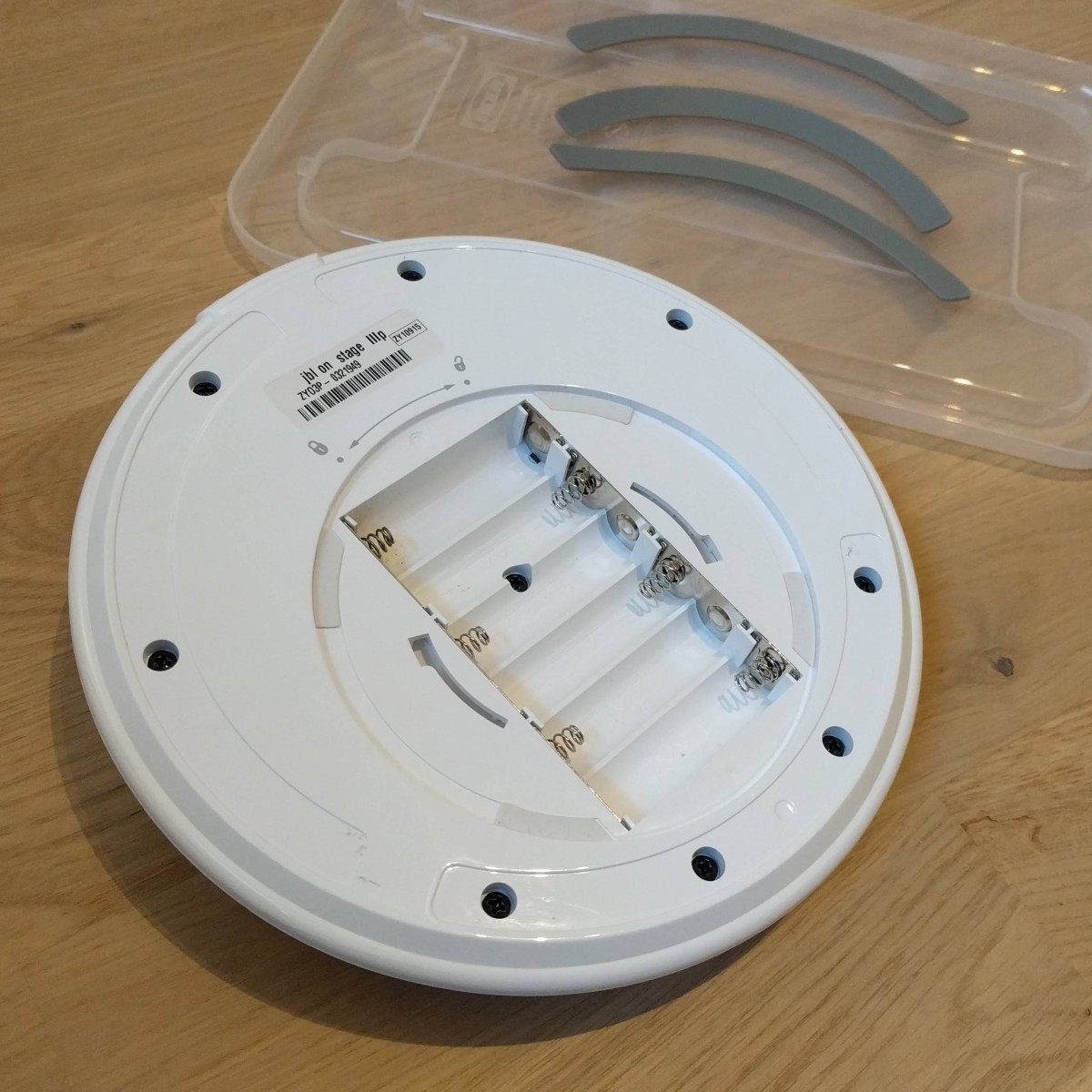
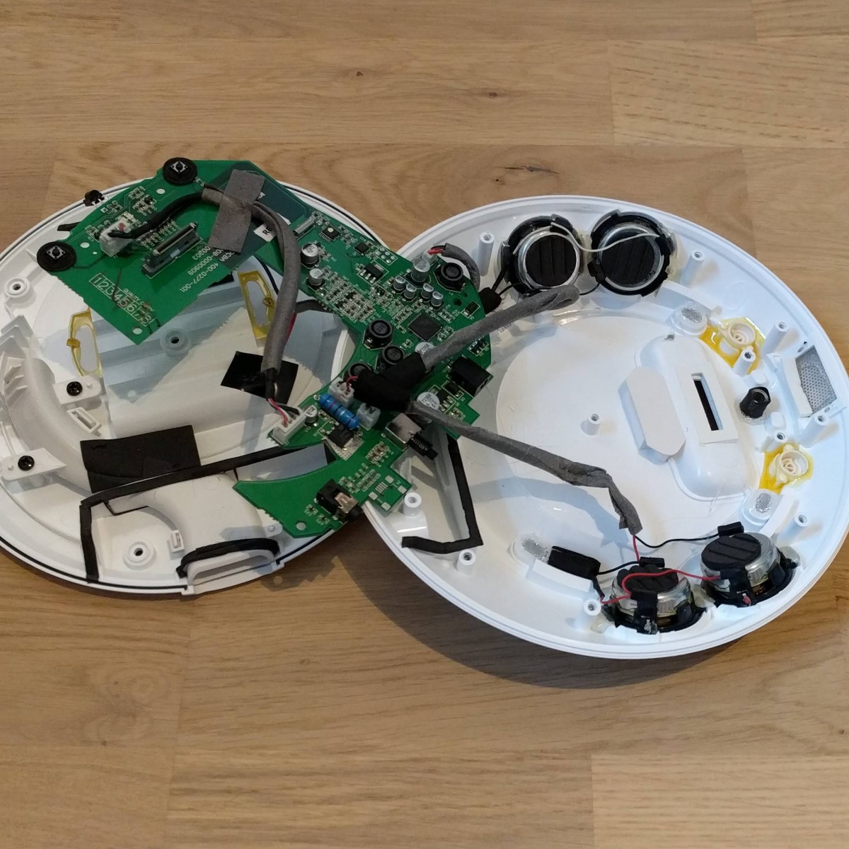
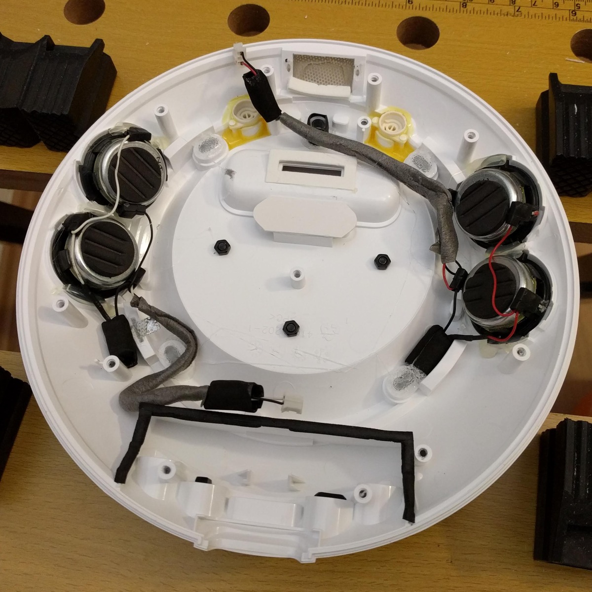
In order to mount the case on the JBL, we have to disassemble the speaker and drill some holes. The screw in the center is hidden in the battery case, while the eight others are hidden under the rubber pads. Just peel them off carefully, we can glue them back on later.
After removing the screws you can upen up the case. The circuit board is fastened with another four screws that have to be removed. Then the board can be pulled out of the case carefully. The power button of the speaker is the most sensitive part here. To make life easier, you can also pull off the speaker cables from the board. Now the cover is completely separated from the bottom and the circuit board.
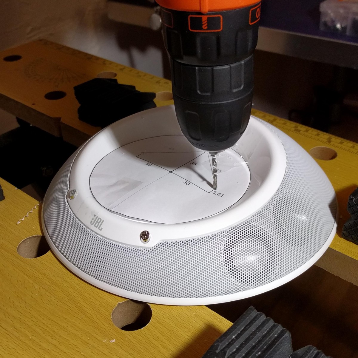
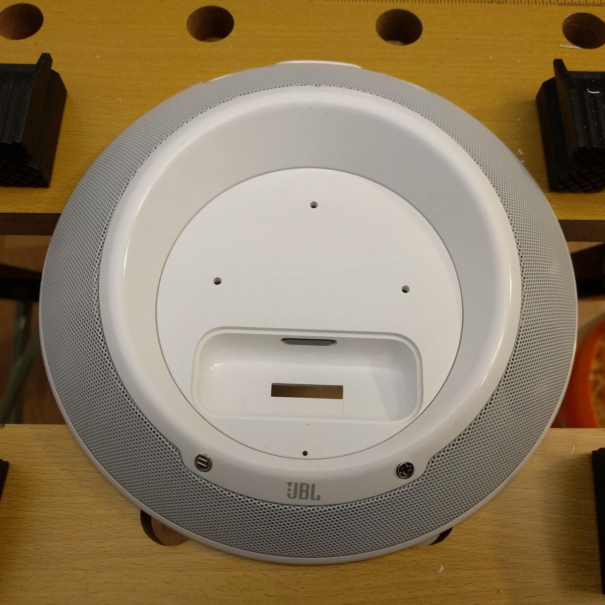
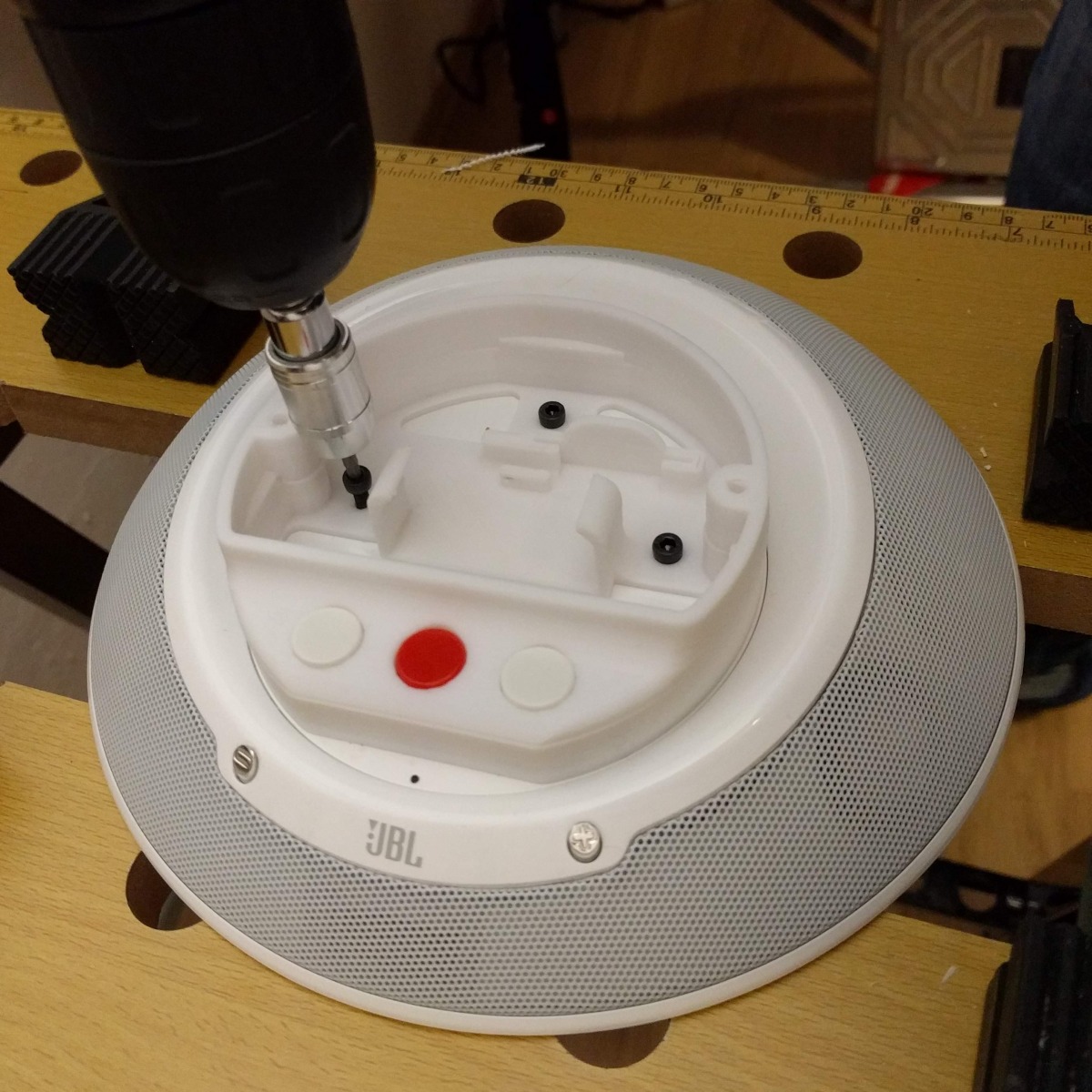
The next step is to drill the three mounting holes into the cover, for which you can use this template. Finally, we need to mount the base of the printed case to the speaker case using thee M3 screws with nuts. Afterwards, we can put the circuit board back in the case and put all the screws back in place.
Putting the Threaded Inserts into the Printed Parts
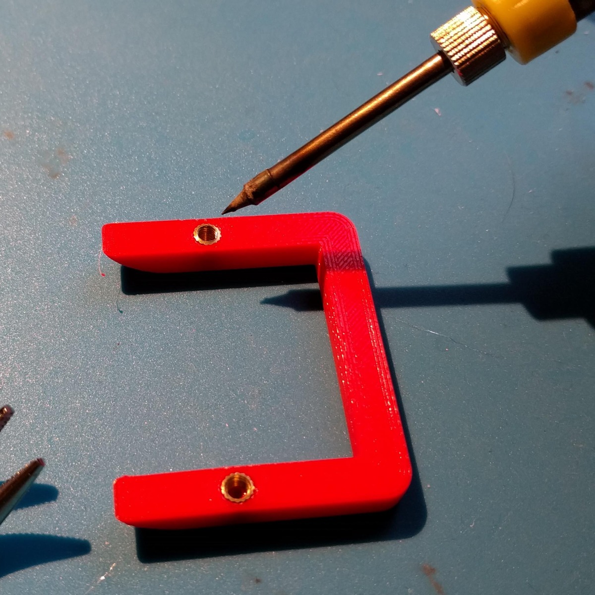
Now is also a good moment to put the threaded inserts into the printed parts. This is done by carefully pushing them into the plastic with a heated soldering iron. As soon as the plastic has cooled down, the inserts will stay in place and allow to close and open the connections without tearing the plastic apart. This video on 3Dhubs shows how it is done.
We put two M3 inserts into the bottom of the case, one into the cover to hold the TCRT5000 sensor and the remaining two into the curb that goes on top of the case.
Installing the Window
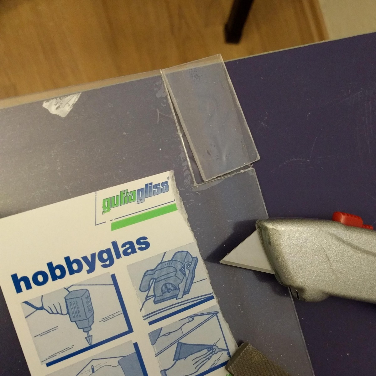
For the window on top of the case, we need to cut a XX mm × XX mm part of acrylic glass. This can be done with a normal cutter knife by (carefully!) repeatedly cutting along your marker line with a ruler until you can break it off. You might need to file the edges a bit until it fits into the slot inside the cover.
When the glass fits into the case, point through the screw holes to mark where you have to drill. The acrylic glass can then be drilled just like the speaker case in the first step.
Wiring
Audio Module
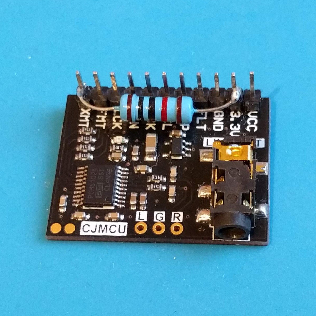
If you are also using the CMJCU-5102 module, you will have to pull the XMT pin to high by connecting it to the 3.3V pin via a 10 kΩ resistor. This will unmute the audio output. Also, the FLT, DMT, SCL and FMT pins should be connected to the module's GND pin on the backside. That way, only a single cable connection to GND on the Raspberry Pi is needed.
The other pins are connected to the Raspberry Pi as follows:
- VCC ↔ pin 2 (5V)
- GND ↔ pin 6 (GND)
- FLT ↔ GND
- DMP ↔ GND
- SCL ↔ GND
- BCK ↔ pin 12 (GPIO 18)
- DIN ↔ pin 40 (GPIO 21)
- LCK ↔ pin 35 (GPIO 19)
- FMT ↔ GND
- XMT ↔ 10k Resistor <–> 3,3V of the PCM5102A board
Buttons
The three buttons go directly in the small pockets on the bottom part of the printed case. While the front pins are put into the small holes in order to fasten them tightly, the pins on the other end should be bent up into a horizontal position. We can easily solder them to jumper cables there and connect to the Raspberry Pi. Connect the buttons to pins 9 (for PREV), 10 (for PLAY/PAUSE) and 11 (for NEXT). The other sides go to the ground pins 20, 30 and 34.
Sensor
The TCRT5000 sensor module is connected as follows:
- VCC ↔ pin 4 (5V)
- GND ↔ pin 14 (GND)
- DO ↔ 29 (GPIO 5)
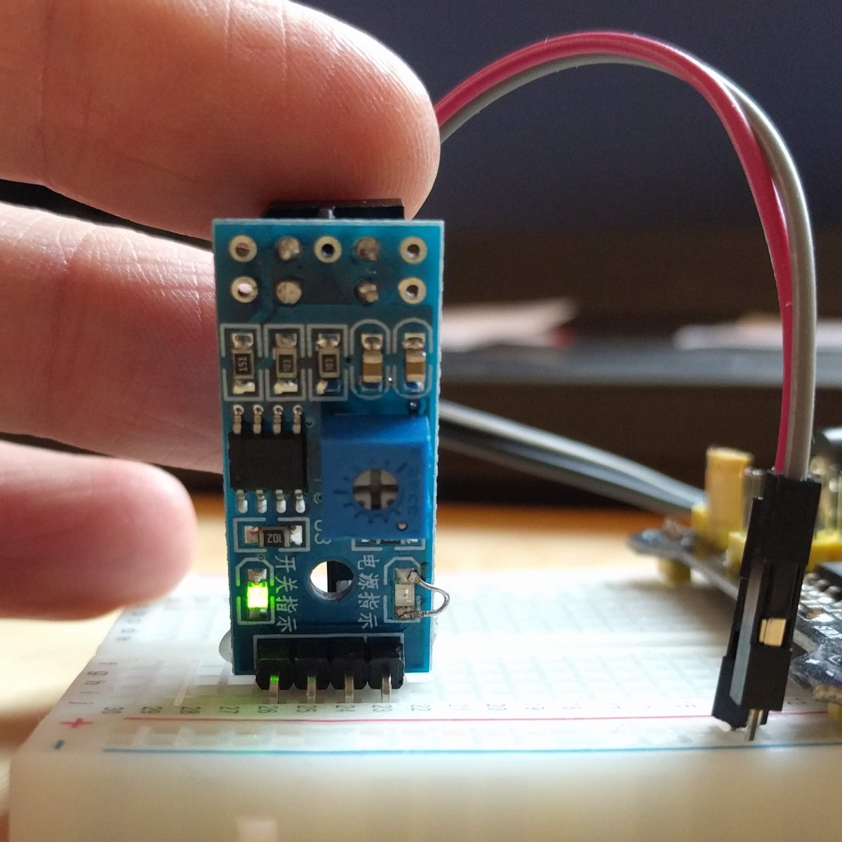
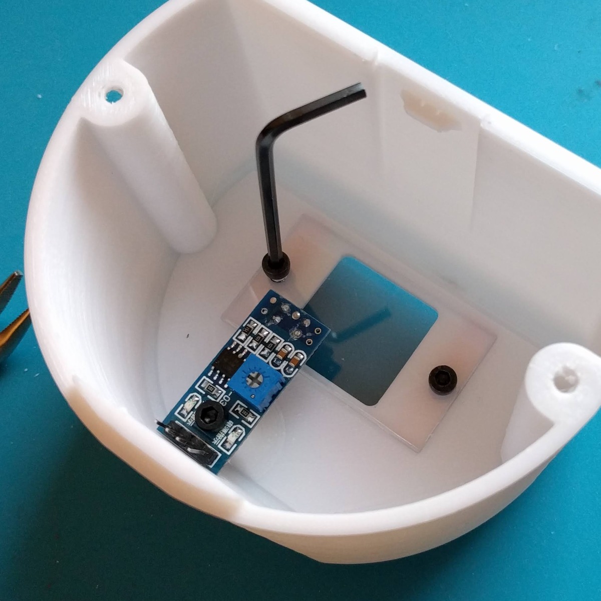
The pins of the module need to be bent up to fit in the case. (For some reason all the modules have 90 degree pins.) We can then use the M3 screw hole to fasten it to the top. The little potentiometer on board allows to adjust the sensitivity of the sensor in place.
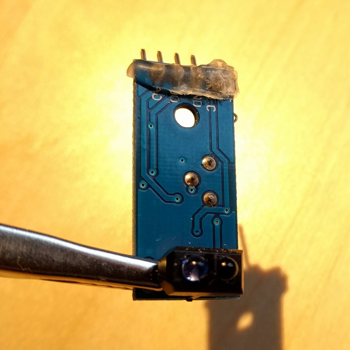
My sensor permanently fired whenever if tightened the scew. Apparently the threaded insert connected two of the pins. I solved this by covering the pins on the back side with some hot glue.
The next problem was a little red LED on the module that was permanently on when the sensor was powered. While being tiny, it put the whole printed case in a permanent red glow that did not look pretty and also would have been disturbing given that the player was to be put on a nightstand. I bypassed the LED with a tiny piece of wire that you can see in the pictures.
LED
The led is put in the small holder at the front side inside the cover. Connect the long leg to pin 15 (GPIO 22) of the Raspberry Pi (with a resistor in between, if needed), the short one to pin 9 (GND). I dimmed the LED with a 100 Ω resistor even though it could work on 3.3 V because it was just too bright.
Software Installation and Configuration
Volumio
Python Script
Configuration und Test
QR Cards
What's Left
If you have any questions or improvements please send me an e-mail to tliero@gmx.net.