AudioSphere
An easy-to-use music player for children based on the Raspberry Pi Zero and the JBL On Stage IIIp
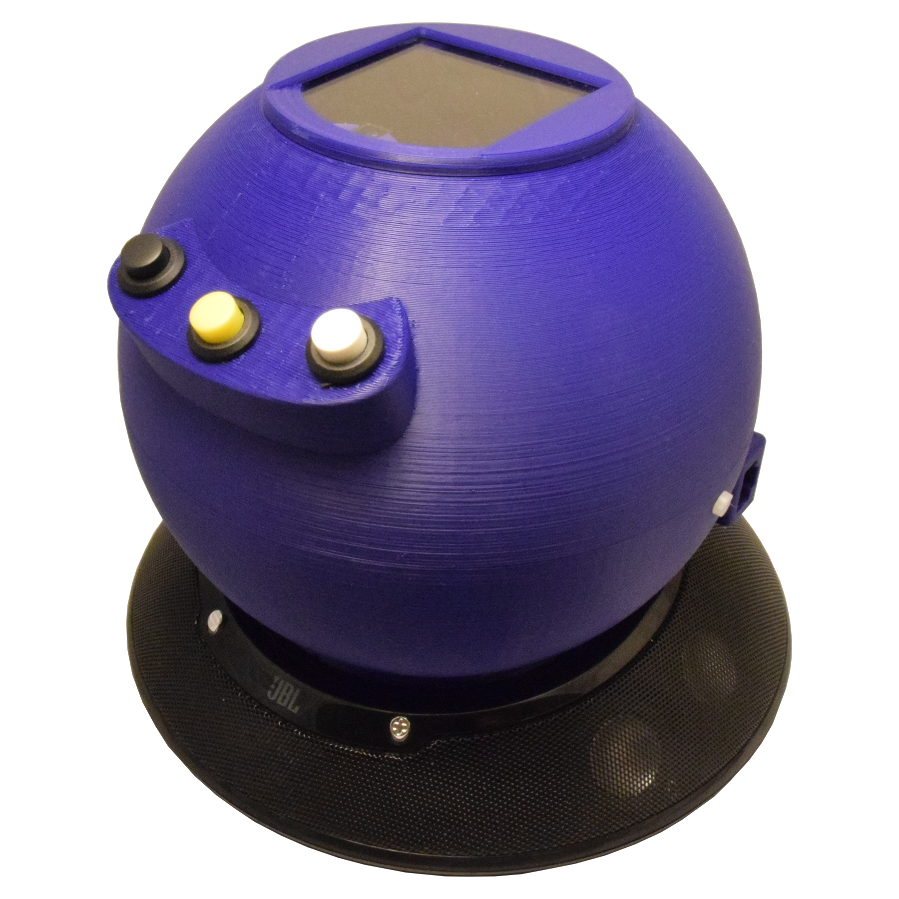
In spring 2016 I finalized the Musikrakete, an MP3 player that our boys could use without assistance. This is the second version: Not a rocket anymore, but with many improvements.
Contents
- The Idea
- PiPlayer, version 2.0: AudioSphere
- 3D Printed Case
- Hardware and Assembly
- Software
- User Manual
The Idea
This project started about a year ago, when Anica asked me if buying a hörbert MP3 player would be a good idea. After all our boys wasted two to three CDs every week, trying to get some music out of the small player in their room. And the player in the living room also seemed to reach its end of life pretty soon due to their enthusiasm. Still I wasn't too sure about the device. In order to get new files on the SD card of the player, the case had to be opened, the navigation with 11 buttons also seemed a little confusing and a single speaker operated with four batteries also did not seem promising to me.
I had seen a project description of an MP3 player for small children shortly before: A Raspberry Pi, connected to a webcam and speakers reads QR codes and plays the respective track or playlist. So this was what I suggested and to my surprise it was considered a better solution right away. And I had a project.
As good as the description seemed to be, I wanted to make some improvements on the original design: The player should detect the QR cards on its own, all components should be put together in a single case and, most important, the MP3 should be delivered directly from our home server. No SD card replacement needed.
Since we had an old JBL OnStage IIIp speaker lying around that wasn't used anymore due to its outdated iPhone dock connector, I decided to use this as a base. After playing around with Onshape, soldering and programming for three months, I had the Musikrakete ready by end of March 2016. It's been a huge success with the boys and has been in heavy use ever since.
But there were still some open ends on the technical side and I knew that we might need a second player, once the boys both have a room of their own. So when Anica was searching for a good gift to her best friend's son we decided that an updated version would be a good idea.
PiPlayer 2.0: AudioSphere
The major improvement in handling was switching from a QR card slot to a window on top where the QR cards are placed on. I had seen that especially the smaller one had problems getting the cards into the narrow slot. Unfortunately, this also meant that a rocket shape was not an option anymore. At first I tried to put only a hemisphere on top of the JBL speaker which would make it look like a UFO. But the webcam needed at least 10 cm distance to the card in order have the entire QR code covered. Technically, it would be possible to further reduce the size of the ball but fitting all the components in there is hard enough as it is. Also, I wanted to be able to use the cards from the first player in the new one as well.
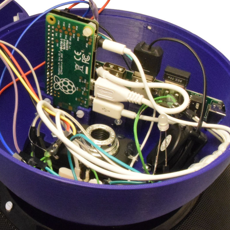
Also, an ethernet port is now available (since we had problems with the Wi-Fi connection in the boy's room) and thanks to switching to the Raspberry Pi Zero, the Apple dock port is now able to provide power for all the components. No additonal power source needed. By incorporating a Pimoroni PHAT DAC I removed all the audio-related headaches.
On the software side there's two major improvements: The SD card is now mounted read-only by default. This makes unplugging the AudioSphere (by accident or for reboot) unproblematic. And the Python script that operates the player now uses interrupts instead of polling for checking the input sources - no more busy waiting!
OK, so much for the overview - let's build this, step by step.
3D Printed Case
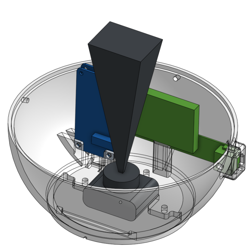
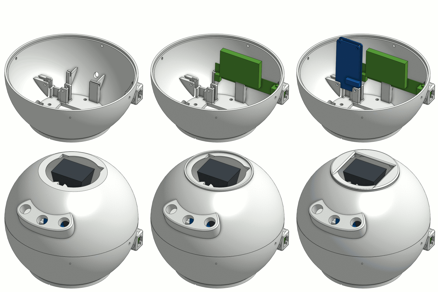
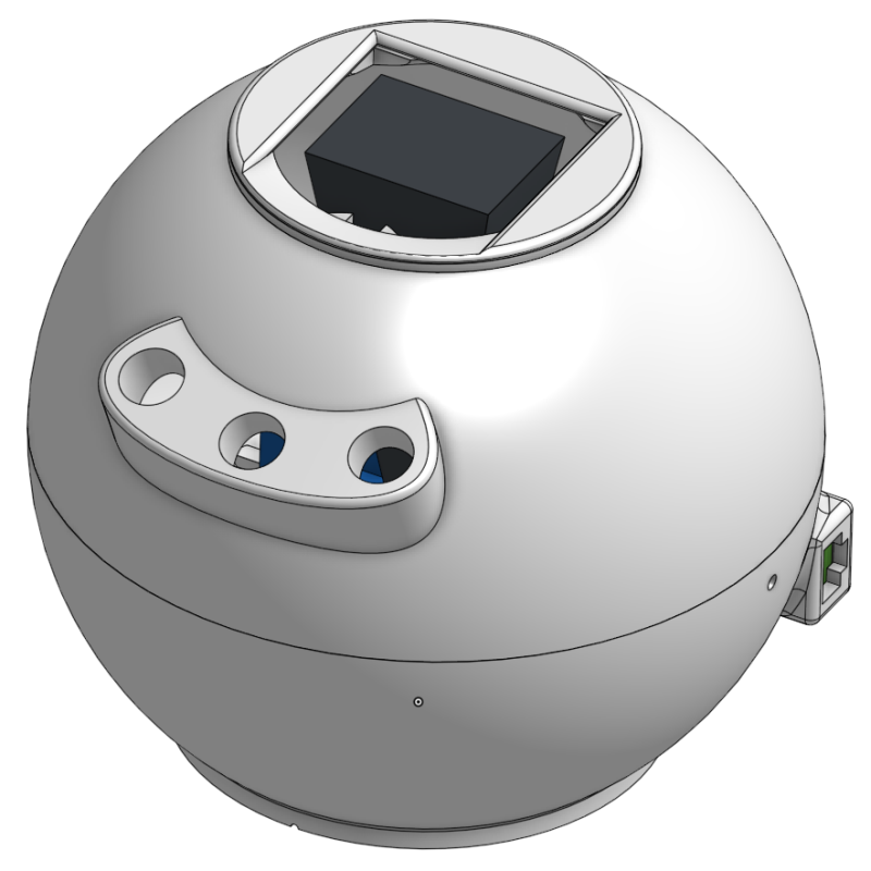
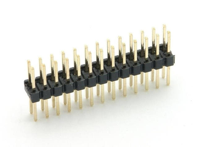
First step was the design of the new case. Like the first rocket case it's public, you can find it here on Onshape. (You will need to create an account to open the document.) Or you can download the STL files for printing if you are using the very same components. Please note that you will need to rotate the top of the sphere 180° for printing. Also be careful about the Raspberry holder: The Raspberry Pi together with the PHAT DAC should have a height of about 7 mm (or less) which depends on the GPIO header that is used to solder the PHAT DAC to the RasPi. If the height exeeds 7 mm the distance has to be adjusted before printing.
Hardware and Assembly
Parts list
- The sphere case, printed via 3dhubs.com
- JBL On Stage IIIP (used via ebay for less than 20 €)
- 3 × M3 screws with nuts and washers for mounting the case on the speaker
- Raspberry Pi Zero with an SD card
- Pimoroni PHAT DAC
- cheap USB Wi-Fi adapter
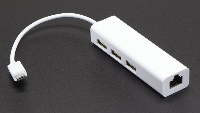
- ultra-cheap Micro USB HUB with ethernet port
- even cheaper USB webcam
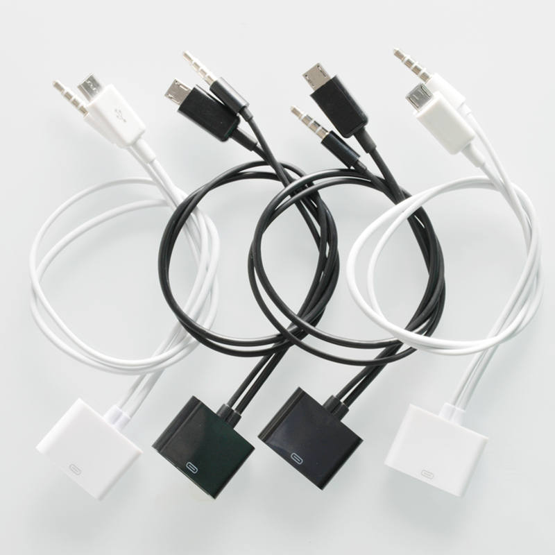
- 30-pin Apple dock adapter to micro USB and 3.5 mm audio
- 2 mm acrylic glass circle with 75 mm diameter. You can order these on ebay.
- 5 × M2.5 screws for the Raspberry Pi and the case
-
Electronic components:
- 3 × 12 mm momentary push buttons
- CNY70 reflective optical sensor
- Resistors: 2 × 100 Ω, 4.7 kΩ, 10 kΩ
- NPN transistor
- White LED for illumination of the QR cards
- Infrared LED (904 nm) for remote controlling the speaker
- Jumper wires
- copper wire, circuit board, solder
-
Tools:
- Soldering iron
- Glue gun
- Screwdriver
- Cutting knife
- Power drill
- Superglue (for the window)
Preparing the JBL IIIp Speaker
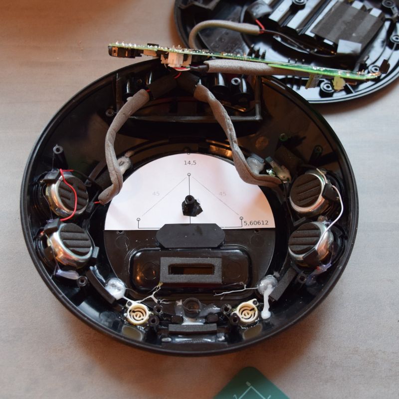
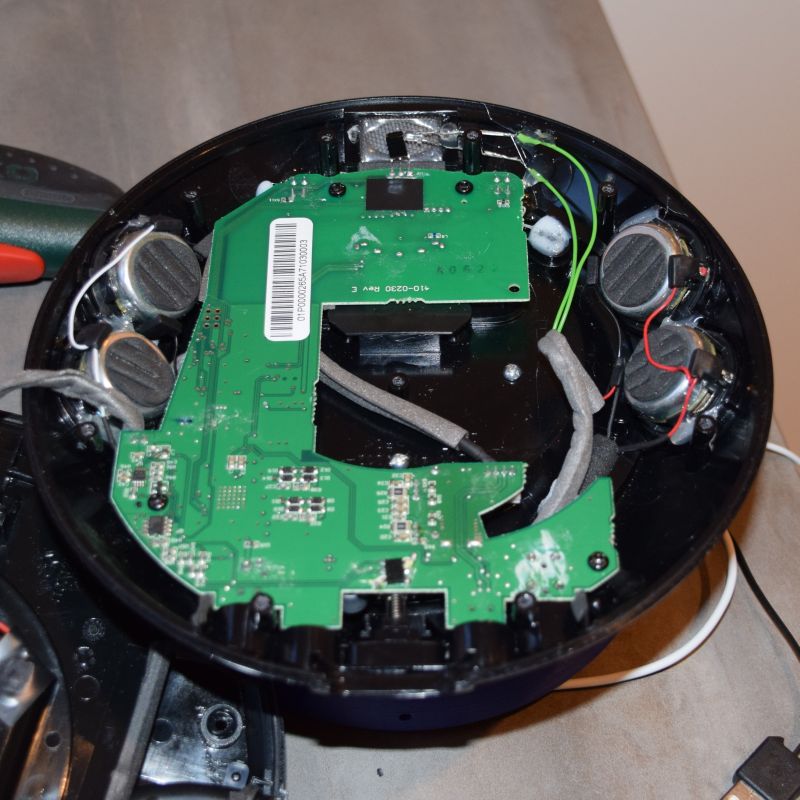
In order to drill the holes for the screws, the JBL On Stage IIIp has to be disassembled. The procedure is described here at ifixit.com for the predecessor which works basically the same way: Remove the rubber pads, then remove all screws from the case. (Don't forget the center screw in the battery case.) Once the speaker case is opened, the circuit board is unscrewed and removed.
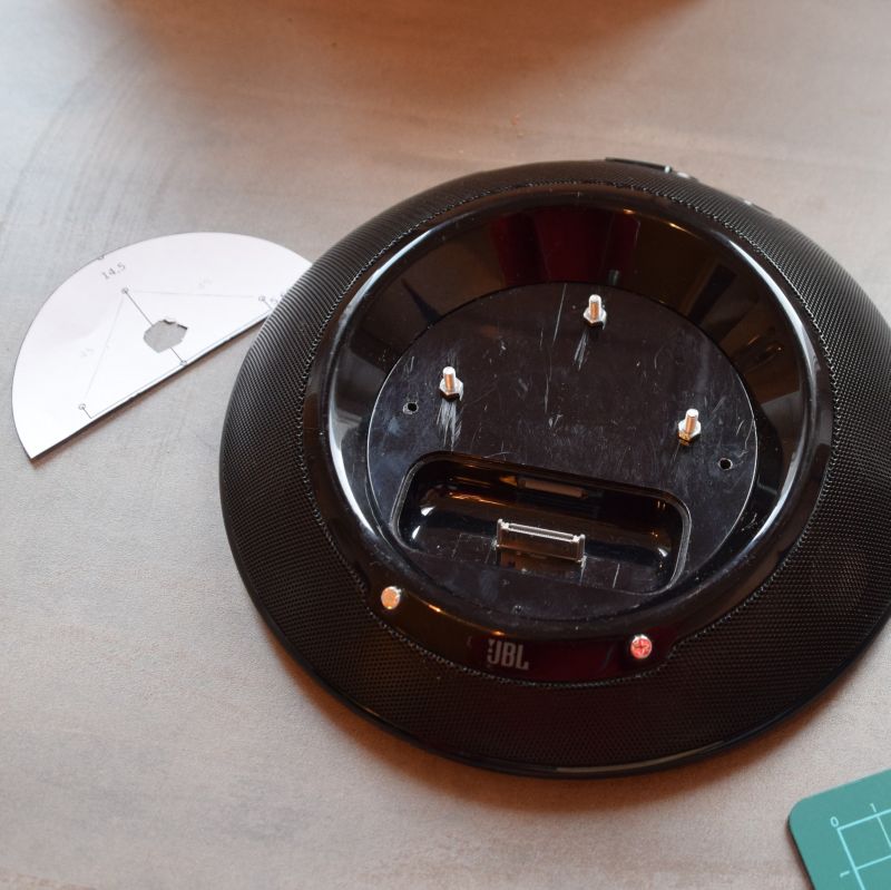
I drilled the holes for the M3 screws and the IR LED cable using a template. The drill itself is set to rotate left. That way, the holes are more or less melted into the plastic to lower the risk of breaking the case.
After drilling, washers and screws are added and the infrared LED is glued directly in front of the speaker's IR sensor in order to send it commands. Before that the PINs of the IR LED are soldered to cables, that are long enough to connect it to the circuit board through one of the additional holes. Also, all the electronics should be tested together before anything is hot-glued into the case.
(Disclaimer: I only did a proof of concept test script for remote contolling the speaker via the IR LED until now. I am planning on using that component later on via a web app but for the time being you could as well leave it out.)
Electronics
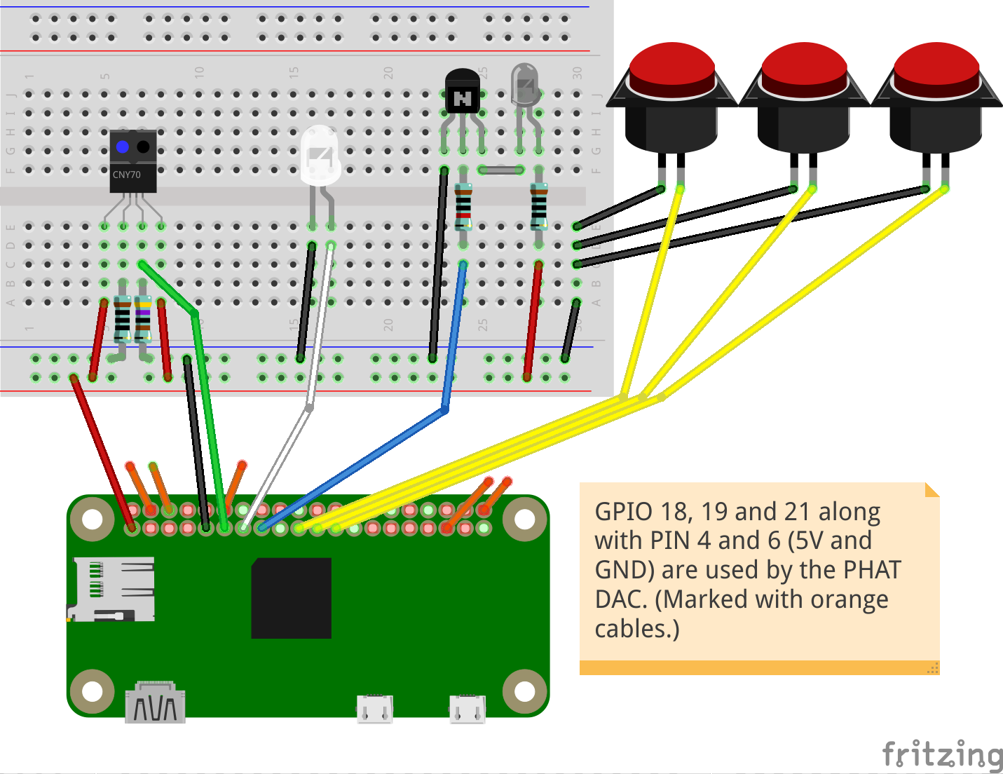
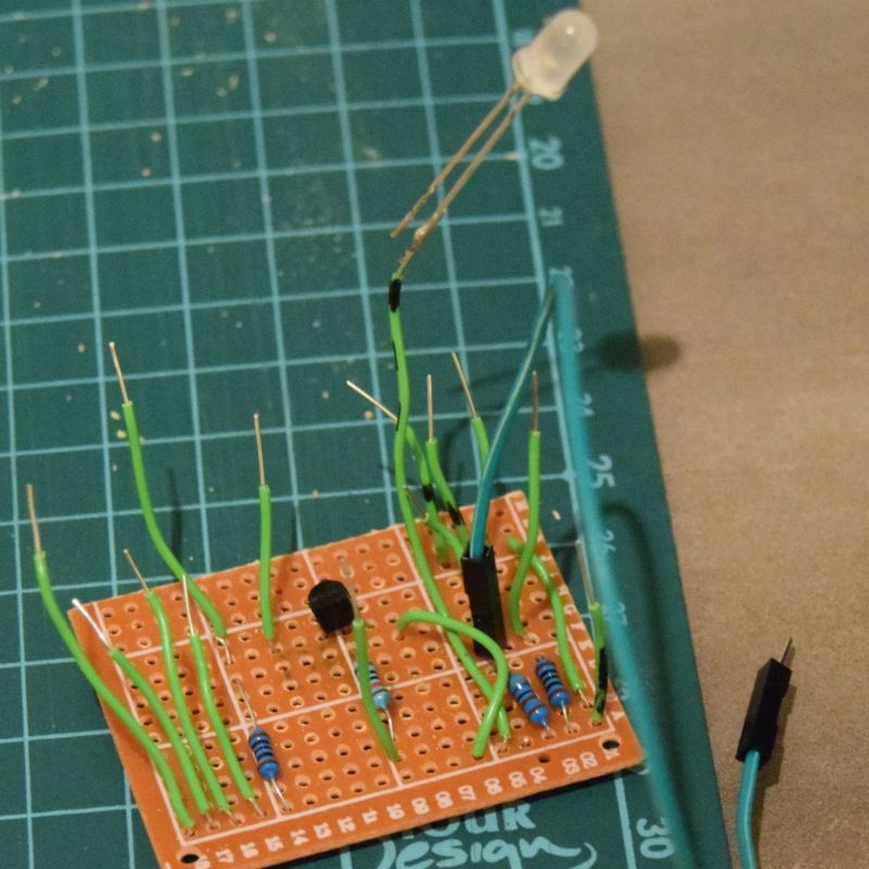
There are four electronic parts: The reflective optical sensor that triggers the QR recognition process, the LED that illuminates the QR card from within the case, the infrared LED that passes commands to the speaker and the 3 momentary push buttions that are used to pause/unpause playback and move within the current playlist. While the buttons and the LEDs are put directly in the case, all other elements are brought together on a circuit board from where they are connected to the RasPi via jumper cables. (Below is a diagram of the electronics and here's the source file for fritzing.)
After soldering the PHAT DAC onto the Raspberri Pi (preferably using a GPIO header that directly routes through all the GPIOs) the used PINs are connected with the jumper cables. Where these were not soldered to the contact, I used hot glue to fix the connection which worked pretty well.
Software
System Installation
Before installing anything additionally, Raspbian Lite has to be installed on the SD card. From there on, it's all on the command line.
Basic setup:
# Make sure that the latest versions are installed
sudo apt update
sudo apt upgrade

# Basic setup: password, keyboard layout, wi-fi channels, hostname, ssh
sudo raspi-config

# Check kernel messages for errors
dmesg

# Check for connected USB devices
lsusb

# Install wi-fi client (https://www.raspberrypi.org/documentation/configuration/wireless/wireless-cli.md)
sudo apt install iw

# Scan networks and add wi-fi network to configuration
sudo iwlist wlan0 scan
sudo nano /etc/wpa_supplicant/wpa_supplicant.conf
#	network={
#		ssid="The_ESSID_from_earlier"
#		psk="Your_wifi_password"
#	}

sudo ifdown wlan0
sudo ifup wlan0

# disable HDMI (http://www.jeffgeerling.com/blogs/jeff-geerling/raspberry-pi-zero-conserve-energy)
sudo nano /etc/rc.local
#	/usr/bin/tvservice -o

# Disable the ACT LED
sudo nano /boot/config.txt
#	dtparam=act_led_trigger=none
#	dtparam=act_led_activelow=off

# Configure NTP
sudo apt install ntp
sudo nano /etc/ntp.conf
# add time server to /etc/ntp.conf
#	server de.pool.ntp.org
sudo /etc/init.d/ntp restart
date

sudo reboot
After the basic installation is done, it's time to bring everything together in the case. All components are connected but we'll wait using the glue gun until everything is tested thoroughly. Especially the webcam might need some in-place live adjustment. The easiest way to do this is by connecting the webcam to another computer while it is already in the case (see bash history below).
Now configure the additional hardware and software that is needed for the player. Before doing that, copy the contents of the piplayer2 directory (including subdirectories sounds and test) to /home/pi (either directly or via SCP). Have also one of the test cards from the template ready for testing the QR recognition.
# Install additional software
sudo apt install lirc zbar-tools mc moc fswebcam python3 python-rpi.gpio python3-rpi.gpio

# Configure PHAT DAC (https://learn.pimoroni.com/tutorial/phat/raspberry-pi-phat-dac-install)
curl -sS get.pimoroni.com/phatdac | bash

# Check for errors
dmesg

# Plug in headphones or JBL connector cable, start mocp and test audio output via the PHAT DAC
mocp -S
mocp -l ~/piplayer2/sounds/scanning.mp3
mocp -x

# Determine the webcams USB ID and the available resolutions (http://askubuntu.com/questions/214977/how-can-i-find-out-the-supported-webcam-resolutions)
lsusb
lsusb -s 001:006 -v | egrep "Width|Height"

# Webcam test: turn on the LED, take a photo and turn the LED off
# (The focus of the webcam should be adjusted before on another computer with a live picture)
python3 ~/piplayer2/test/lighton.py
sudo fswebcam -r 320x240 -d /dev/video0 -v ~/webcam-test.jpg
python3 ~/piplayer2/test/lightoff.py

# Copy ~/webcam-test.jpg to another computer and have a look at it
# If needed, adjust the webcam and repeat the step until the QR code recognition is reliable

# QR-Test: Hold a QR code card above the webcam then turn on the LED, decode the QR code and turn the LED off
python3 ~/piplayer2/test/lighton.py
zbarcam --quiet --nodisplay --raw -Sdisable -Sqrcode.enable --prescale=320x240 /dev/video0
python3 ~/piplayer2/test/lightoff.py

# Enable lirc in /boot/config.txt and add parameters
sudo nano /boot/config.txt
#	# Uncomment this to enable the lirc-rpi module
#	dtoverlay=lirc-rpi,gpio_in_pin=23,gpio_out_pin=22

# add lirc configuration to /etc/lirc/hardware.conf
sudo nano /etc/lirc/hardware.conf
#	LIRCD_ARGS="--uinput"
#	LOAD_MODULES=true
#	DRIVER="default"
#	DEVICE="/dev/lirc0"
#	MODULES="lirc_rpi"
#	LIRCD_CONF=""
#	LIRCMD_CONF=""

sudo reboot
When everything works as expected, everything is fixed together using hot glue. I glued the webcam, the circuit board and the USB hub in place so that nothing will fall out of place anymore, even if the player is moved around roughly.
While I really like hot glue, it's got its limits: I thought I could skip soldering the buttons to their wires by just twirling the cable ends to the contacts and then fix everything down with the hot pistol - bad idea. While being hot, the glue gets in between the wire ends and the contacts and perfectly isolates them. None of the buttons worked anymore. I had to peel the glue off the contacts with a cutter knife before soldering them properly back on again...
Now that everything is in place, we are ready for the final adjustments: Configure autostart for the player script and mount the SD card in read-only mode which makes the player robust against sudden loss of power. For that, we redirect the write access to a RAM disk.
# Autostart for piplayer2.py with log output redirection (http://raspberrypi.stackexchange.com/questions/8169/run-startup-application-as-a-specific-user)
sudo nano /etc/rc.local
#	...
#	su pi -c 'python3 /home/pi/piplayer2.py >> /home/pi/piplayer2.log 2>&1 &'
#	exit 0

sudo reboot

# Check if running after restart
ps -ef | grep python

# Watch the log output while testing with QR code cards
tail -f /home/pi/piplayer2/piplayer2.log

# Switch to RAM disk and set the filesystem read-only (https://www.heise.de/ct/ausgabe/2016-21-Den-Raspi-als-Bluetooth-Empfaenger-einsetzen-3330683.html)

sudo nano /etc/fstab
#	proc            /proc            proc    defaults                      0       0
#	/dev/mmcblk0p1  /boot            vfat    defaults,ro                   0       2
#	/dev/mmcblk0p2  /                ext4    defaults,noatime,ro           0       1
#	tmpfs           /var/log         tmpfs   nodev,nosuid                  0       0
#	tmpfs           /var/tmp         tmpfs   nodev,nosuid,mode=1777        0       0
#	tmpfs           /tmp             tmpfs   nodev,nosuid,mode=1777        0       0
#	tmpfs           /home/pi/.config tmpfs   nodev,nosuid,mode=1777,uid=pi 0       0
#	tmpfs           /home/pi/.moc    tmpfs   nodev,nosuid,mode=1777,uid=pi 0       0
#	# a swapfile is not a swap partition, no line here
#	#   use  dphys-swapfile swap[on|off]  for that

sudo rm -rf /var/lib/dhcp/ /var/spool /var/lock /etc/resolv.conf
sudo ln -s /tmp /var/lib/dhcp
sudo ln -s /tmp /var/spool
sudo ln -s /tmp /var/lock
sudo ln -s /tmp/resolv.conf /etc/resolv.conf

# make /tmp on RAM disk writable
# shown here with the former additions to rc.local - note that the log redirect for the player script is changed also
sudo nano /etc/rc.local
#	...
#
#	# make /tmp on RAM disk writable
#	chmod 777 /tmp
#
#	# disable hdmi
#	/usr/bin/tvservice -o
#
#	# start piplayer
#	su pi -c 'python3 /home/pi/piplayer2.py >> /tmp/piplayer2.log 2>&1 &'
#
#	exit 0

sudo reboot
We can make the filesystem writeable again for maintenance by remounting it like this:
# Dateisystem temporär beschreibbar machen
sudo mount -o rw,remount /
sudo mount -o rw,remount /boot
Until now, we can only play local files from the SD card (and audiostreams from the Internet). The final step is to connect the local share that stores all of our MP3 files. How this is done depends upon the type of share you would like to use. The most common type should be a SMB share that can be connected like this:
HIER WEITER: Test-MP3 zu Template und Repository hinzufügen
# Share einbinden
sudo nano /etc/rc.local
#	sudo mount -t cifs -o user=guest,password= //192.168.1.125/media /home/pi/share

# via /etc/fstab HAT NICHT FUNKTIONIERT
sudo nano /etc/fstab
#	tmpfs           /media/share     tmpfs   defaults,size=10%             0       0
#	//192.168.1.125/hidrive/Media /media/share cifs guest,ro